
Waste To Energy System
SIMPLE PROCESS FLOW
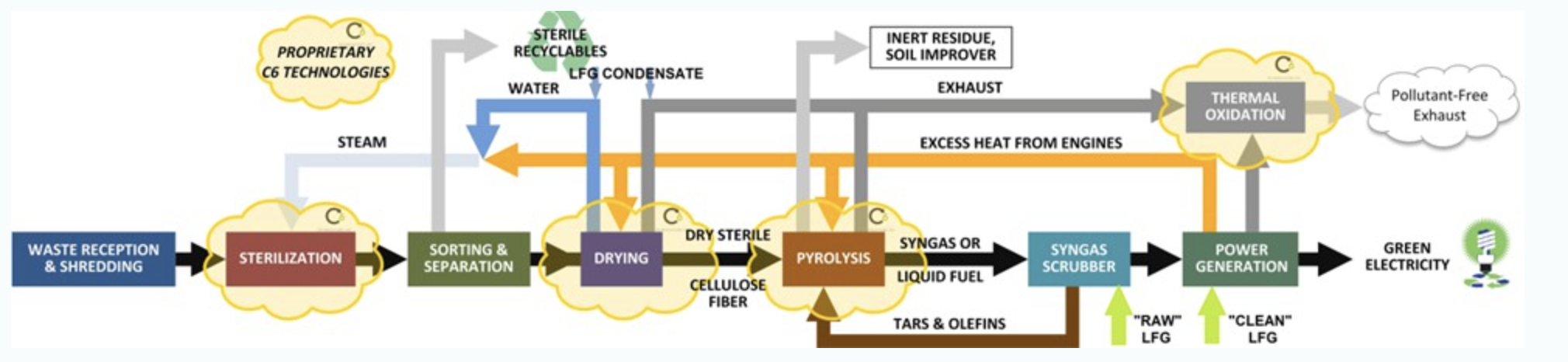
Waste reception will be dictated by the location of the facility and waste types and is likely to be trucks delivering various forms of waste, the most common being Municipal Solid Waste (MSW).
The size of the waste must be such that it can fit in the autoclaves, dryers and pyrolyzers, therefore large items such as mattresses and tires need to be reduced in size via a shredding process.
Sterilization
For projects taking in raw MSW, waste will pass through the autoclave, which utilizes heat, steam and pressure to sterilize the waste. There is no need to either pre-shred or open trash bags prior to loading into the autoclave as the internal agitation in this unit performs this function. The autoclave process gives a very high pathogen and virus kill rate. Note: tires, wood and certain other feedstock do not require sterilization. The autoclaves are considered the elegant solution for processing raw MSW.
Separation of Recyclables (Potential phase 2 upgrade)
Sterilized recyclables such as glass, ferrous and non-ferrous metals are removed, and non-pyrolyzable materials such as aggregates are also removed. Depending on local market conditions, sterilized plastic can be removed either for resale, for conversion to on road diesel fuel and naphthas, or it can be used for its energy value as part of the feedstock being converted to electricity.
Drying
Pyrolysis feedstock is passed to the dryers. Excess moisture in the feedstock is removed before it is sent to the pyrolyzer. Following the drying processes, waste is homogenized and reduced in size to less than 4mm. In some instances, the reduction equipment may be positioned before the dryer. At this stage the dry, input, commonly known as Refuse Derived Fuel (RDF grade 3, or “fluff” RDF), is fuel for the pyrolyzer. The project will be receiving RDF. It is anticipated that the fuel will still need to pass through a dryer to reduce moisture content before entering the pyrolyzer.
Pyrolysis
Pre-Conditioning: various processing treatments are carried out on the waste in preparation for pyrolysis. The process or processes required are be dependent on the nature of the waste. Pyrolysis: Once treated, the feedstock is passed into the pyrolyzer. It uses a high temperature in the absence of oxygen to convert waste into syngas. Syngas is predominantly a mixture of methane, hydrogen and carbon monoxide.
Syngas Cleaning
Tars, oils, aerosols and “fines” are removed from the syngas using variable condensing temperatures and scrubbing systems. These molecules are then cycled back through the Pyrolyser to ensure they are broken down further. Tars are vitrified along with any residue, providing the heat input to the Pyrolyzer, avoiding the use of the syngas for this purpose, and increasing overall project efficiency.
Electricity Production
Clean syngas is passed from the pyrolyzer either directly into an engine with a generator set or using a turbine to generate electricity. The electricity generated by gas engines and/or turbines is exported to the grid.
Emissions Control
Combined exhaust from the dryers, pyrolyzers and engines is progressed through a regenerative thermal oxidizer, ensuring that the final exhaust discharge to atmosphere meets worldwide emissions acceptance criteria.
PYROLYSIS
The vast quantities of waste produced around the World represent a large and growing problem for governments and for the companies and communities that must dispose of it. They are seeking ways to avoid landfill costs for those types of waste not amenable to recycling. Incineration is no longer a viable solution. Simultaneously, the days of cheap and abundant fossil fuel are over and attention is increasingly turning to renewable forms of energy production.
FLAG ETS provides a solution to the above stated problems as well as various other benefits:
* Continuous Renewable Energy: Renewable, Green Energy that is not dependent on wind, sun or other climatic conditions;
* Reduction in New Landfills, Rehabilitation of Existing Landfills & more efficient and focused method of Waste Disposal;
* Reduction in Incineration: FLAG ETS Plants eliminate the need for incineration of non-recyclable waste;
* Pollution and Emissions Reduction: Elimination of harmful emissions and other pollutants;
* Employment: Creation of new jobs in the construction, operation and maintenance of FLAG ETS facilities.
PYROLISATION PROCESS
Basic explanation of the chemical reactions that take place during the Pyrolisation Process:
Organic compounds will, if heated in a controlled manner, break down into lower molecular weight compounds, changing physical form as their molecular weight decreases. Within this reaction, organic solids will be converted first into liquids and then into gases. On the basis that heating is achieved in an oxygen-starved environment, the thermo-chemical decomposition process is termed gasification. Pyrolysis is an advanced form of gasification and takes place at elevated temperatures in the absence of oxygen. Pyrolysis is capable of treating many different solid hydrocarbon-based wastes. Pyrolysis and gasification are dissimilar to burning, which requires oxygen.
Pyrolysis can be used to produce gas or liquid products. Pyrolysis can produce a clean fuel gas mixture of methane, carbon monoxide and hydrogen called “syngas”. This syngas will typically have a calorific value of 19 - 30 MJ/m3 depending on the waste material being processed. The lower calorific value is associated with biomass waste, the higher calorific value being associated with other wastes such as sewage sludge. Gases can be produced with higher calorific values when the waste contains quantities of materials with a high calorific value, such as rubber. Pyrolysis can also be used to produce liquid fuel, similar to diesel, which can be readily stored and transported. Syngas is suitable for utilization in either gas engines to generate electricity, or in boiler applications. Syngas burns more efficiently and cleanly than the waste from which it was made.
Biomass pyrolysis can thus improve the efficiency of large-scale biomass power facilities such as those for forest industry residues and specialized facilities such as black liquor recovery boilers of the pulp and paper industry, both major sources of biomass power. Like natural gas, syngas can also be burned in gas turbines, a more efficient electrical generation technology than steam boilers to which solid biomass and fossil fuels are limited. Our pyrolysis process has successfully operated gas engines utilizing many different biomasses as the feed source.
During the gas cooling phase a gas clean-up system is employed to render the syngas “engine friendly”. Pyrolysis leaves a solid inert residue of between 10 to 15% of the biomass processed. This can be used in a residue beneficiation process or low value applications such as road fill or brick-making, with the worst case scenario of non-hazardous landfill.
BASIC PYROLYSIS PLANT
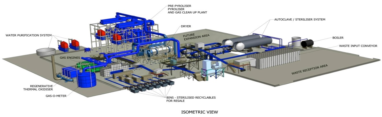
DRYER
Dryers are used to reduce the moisture content to a predetermined range and thereby increase pyrolyzer efficiency. Recycled heat from the engines is used to minimize feedstock drying costs and increase overall project efficiency. The dryers can process all materials e.g. cellulose fibre from autoclaves, wood waste, etc. and achieve accurate output moisture content by monitoring and controlling the exhaust. An efficient twin drum design allows loading and unloading from one end and reduces the unit’s overall length. Material handling through a sealed hopper and auger eliminates dust. An extremely reliable four-wheel drive rotates the dryer so that internal tumblers and compression plates homogenize any feedstock.
PYROLYZER
This patented piece of equipment is at the heart of the technology advanced recycling and energy conversion process. The dried cellulose fibre material is thermally decomposed at high temperature in the absence of oxygen (non-burn) to produce syngas. The pyrolysis process takes place at a temperature in excess of 900°C. The pyrolyzer consists of two stages. The first, or pre-pyrolyzer, pre-heats the material to a temperature that depends on the material being processed. An inner drum is rotated within a heated outer vessel. The temperature of the outer vessel and the speed of rotation enable the material exit temperature to be precisely controlled. The material then passes through to the pyrolyzer unit, which also consists of a totally sealed inner unit surrounded by a heated outer vessel. After initial start-up using external fuel, the pyrolyzer is heated to a temperature of 950°C using a small quantity of the syngas that it generates.
The system is very efficient with a parasitic load of around 10%, vs. competitive systems that typically consume 25% of the power produced. As the material moves through the chamber, angled distribution plates control the retention time in the system. Multiple offtake points allow the composition of the gas to be precisely controlled. The syngas produced has a very high calorific value (CV), typically 22 MJ/m3, compared to competitive systems that typically achieve less than 8 MJ/m3. A high volume of gas and thus electrical energy is generated, typically 1.1 MW per ton for materials with nominal CV of 16 (competitive systems achieve less than 0.7MW/ton).
The design of the equipment involves no high-temperature moving parts (unlike competitor rotary kiln-type designs) and ensures no gas leaks. All carbonaceous material is converted with no char remaining (unlike gasification) and no fines are carried over to the gas clean-up system. The system is very thermally efficient, with remaining low-grade heat being used to preheat air going to the burners and pyrolyzer exhaust being used to heat the pre-conditioning system. The entire system can be pre-assembled to minimize site construction.
SYNGAS SCRUBBER
Syngas is passed through condensers which are designed to ensure that all entrained tars, waxes and oils ‘fall out’ of the gas stream. There are no discharges of tar, oil or wax from the process. The condensers are periodically back flushed to remove the tars, oils and waxes and the wash liquid is reintroduced into the pyrolyzer to ensure these molecules are further broken down. The syngas is then cooled within two wet scrubbers of counterflow direct contact design, which use a water spray to remove the “fines”, thereby preventing damage to the downstream equipment and reducing particulate emissions. The temperature of the syngas as it exits the scrubbing system is between 40°C and 15°C. Finally, the scrubbed syngas is stored under pressure in the gasometer storage tank and is available to power gas engines to generate electricity.
THERMAL OXIDIZER
Exhaust gases from the dryers, pyrolyzer burners, engines and turbines are sent to regenerative thermal oxidizers to remove pollutants to a level of less than 16 parts/million. Most Environmental Agencies require all air emissions to be heated to 850°C for more than 2 seconds, typically requiring high energy consumption. The technology design reduces energy consumed to approximately 15% of competitive designs. This is accomplished by using a bi-directional design. Gases acquire heat from a ceramic bed at one end and deposit it at a bed at the other end prior to discharge to the stack. Flow is reversed every 90 seconds to allow the previous exit heat sink to heat the incoming gases. The last 15% of the required heat is supplied by syngas produced by the pyrolyzer. The unit removes all volatile organic compounds and easily meets the EU environmental emissions laws, as well as US EPA regulations. It operates effectively from full load to a fraction of output. In the event of high concentrations, NOX can be reduced by 90% and neutralizers can be added to treat otherwise difficult compounds.
CONTINUOUS EMISSIONS MONITORING EQUIPMENT
Continuous emissions monitoring equipment (CEM) is located on the exhaust stack, which is the sole emissions point of the plant. Emissions will conform to all local and federal regulations and standards. The CEM monitors all contaminants and emissions as required by US EPA regulations. The CEM operates continuously on a 24-hour basis and will include a facility for on-line monitoring of gas concentrations and will provide notifications of any out-of-tolerance indications which are then sent to both on and off-site staff. The CEM equipment is subjected to an annual surveillance test.
Parallel calibration with the reference methods occurs at least once every three years. Automated reports from the CEM will be made available to local inspectors. Periodic measurements of non-continuously monitored pollutants and heavy metals will be undertaken in accordance with the timescales laid down by the local authorities within the Environmental Permits.
FLAG ETS, LLC